Login
Please use your Danfoss credentials to log into the System Selection Tool.
Log in:

Please use your Danfoss credentials to log into the System Selection Tool.
The Danfoss System Selection Tool helps us to ...
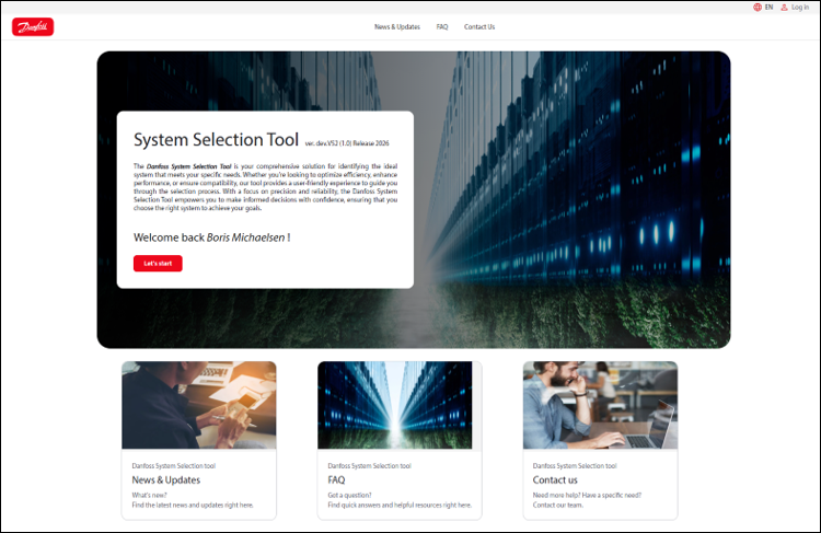
Go to System Selection tool and press "Lets Start"
The System Selection Tool is an engineering application designed to help users find the most suitable refrigeration or heat pump system for a given operating point. By entering a few key parameters — such as the desired capacity, temperatures and refrigerant — the tool automatically pre-selects, simulates and evaluates hundreds of possible system configurations. The results are ranked by efficiency (COP), operating costs (OPEX) and capital investment (CAPEX), enabling the user to make a well-informed decision. A detailed report including system diagrams and part-load performance can be generated for each selected system.
The tool covers single- and multi-compressor systems as well as single- and two-stage cycle designs. It supports various refrigerants (e.g. R1234ze, R515B) and a wide range of coolant media. Behind the scenes, physical system models (FMUs) are simulated dynamically — including the complete control logic — to determine realistic performance data at the operating point and across the full part-load range. Heat exchangers are sized automatically based on the requested capacity and temperature differences.
This guide walks through every step of the workflow: from creating a project and defining the use case, through the automated selection and simulation process, to reviewing results, comparing systems and generating a customer-ready report with bill of materials, CAPEX and OPEX analysis.
What such a tool must be able to do:
Workflow:
The landing page contains contact details, frequently asked questions and information about updates to the tool.
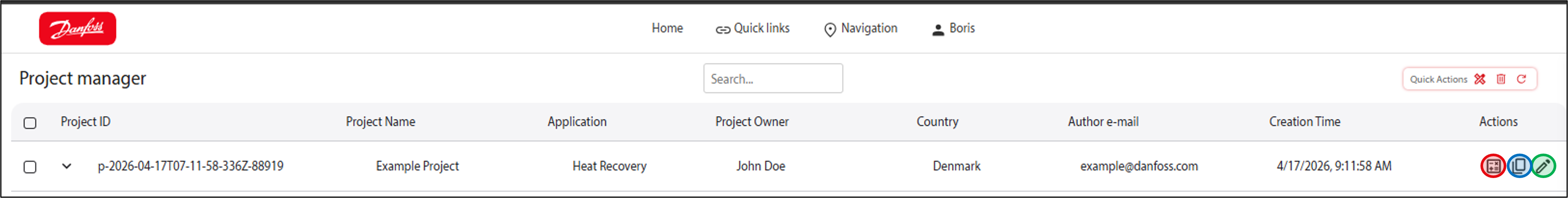
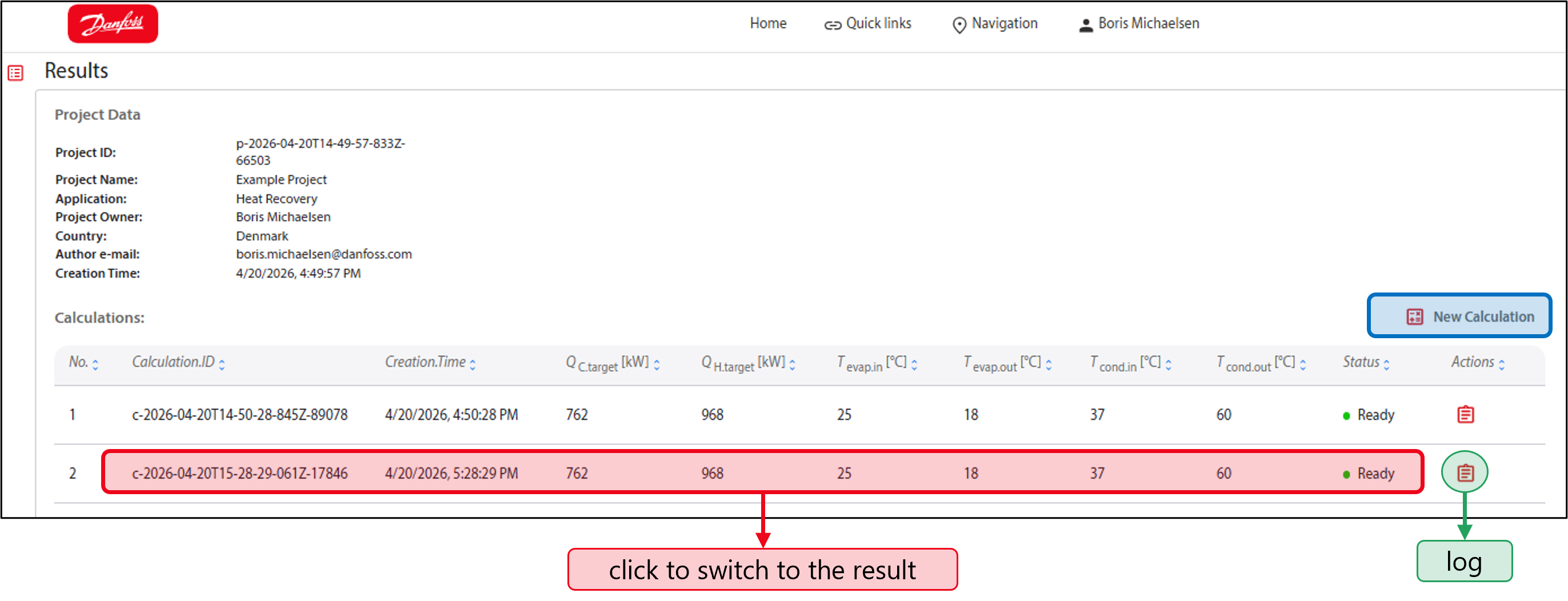
Once you've started, you'll see an overview of your projects and can create new ones.
Define project metadata
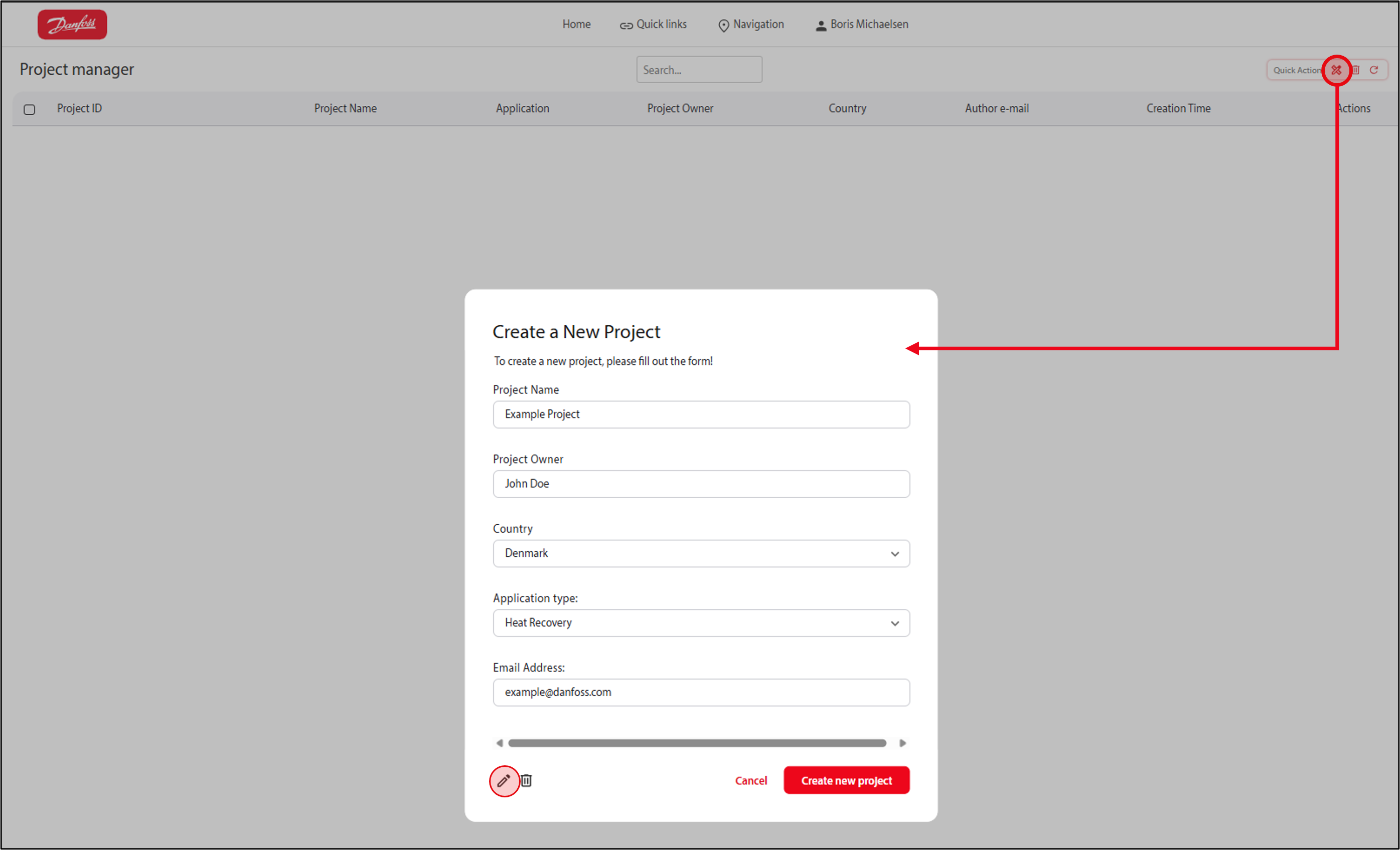
Manage your projects
Create new system selection by starting a calculation
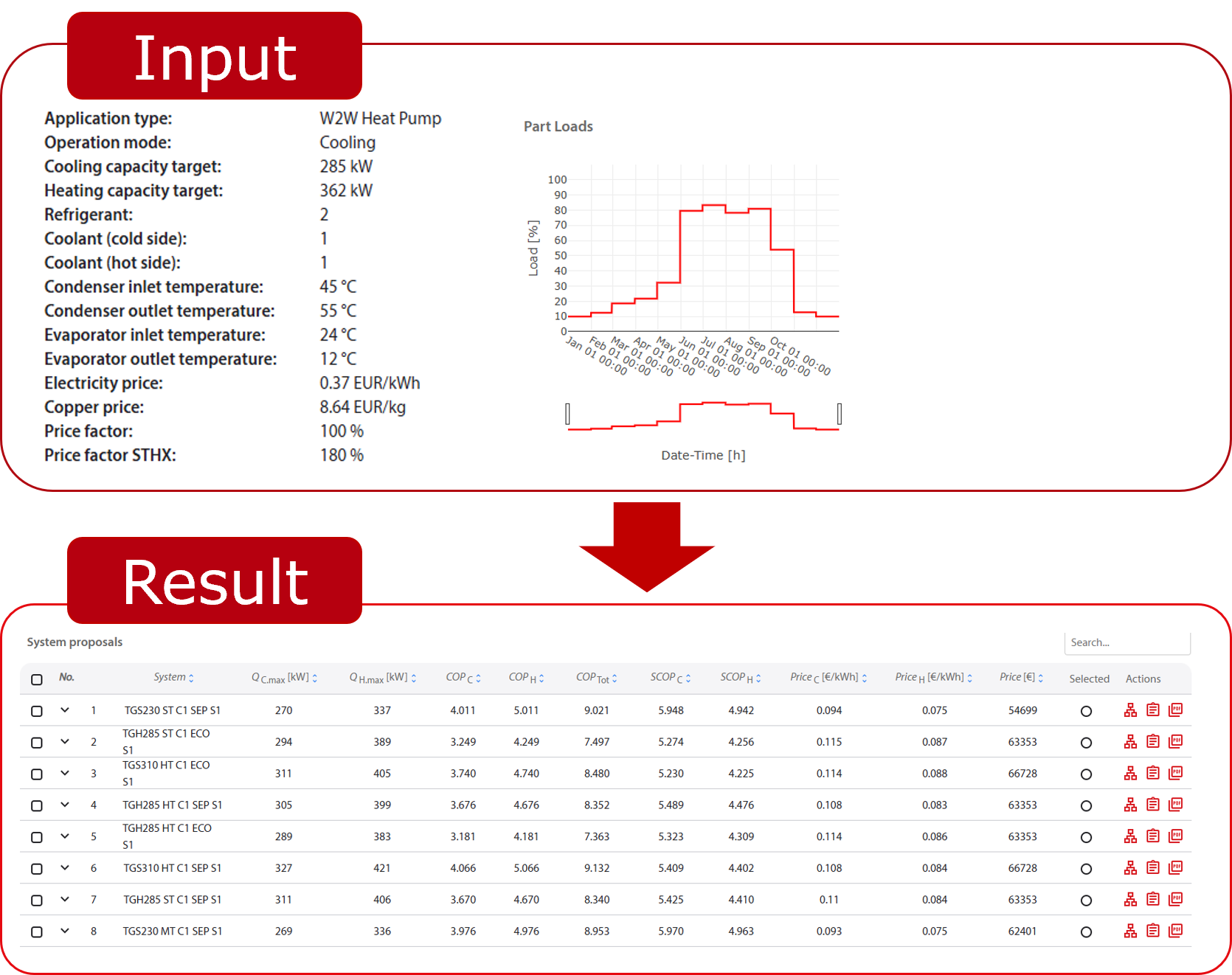
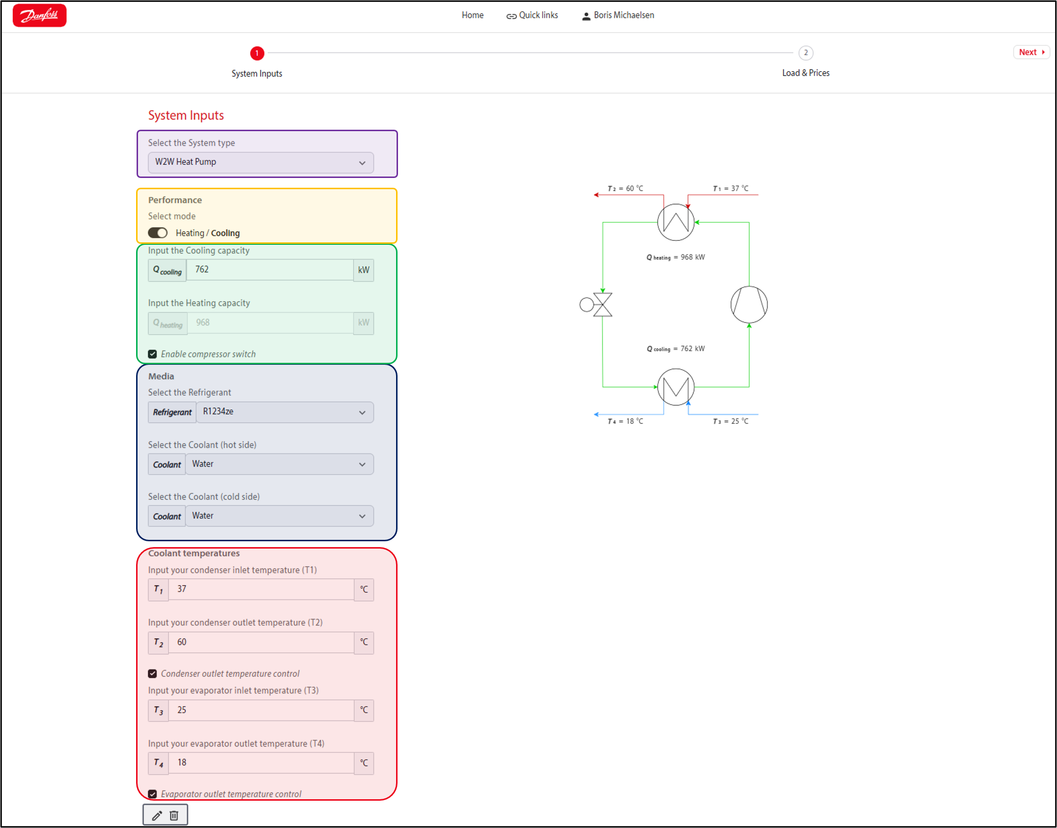
Use case (operation point for system sizing)
Tool connectivity
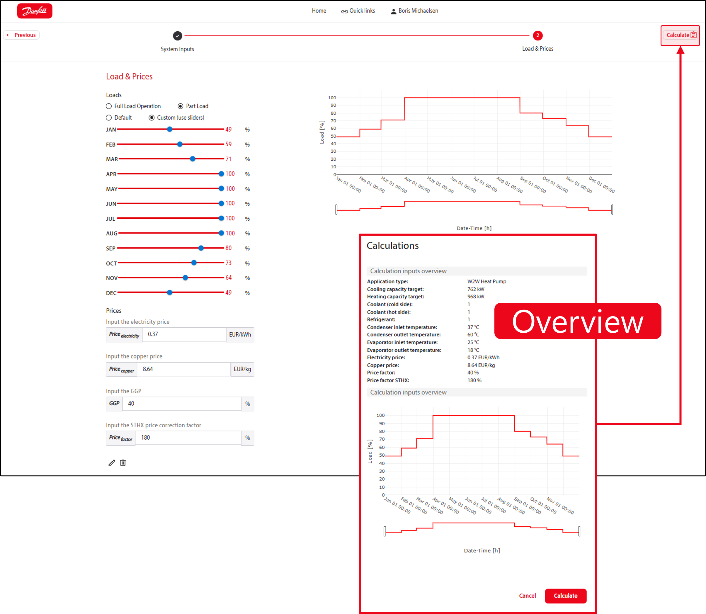
Input actions
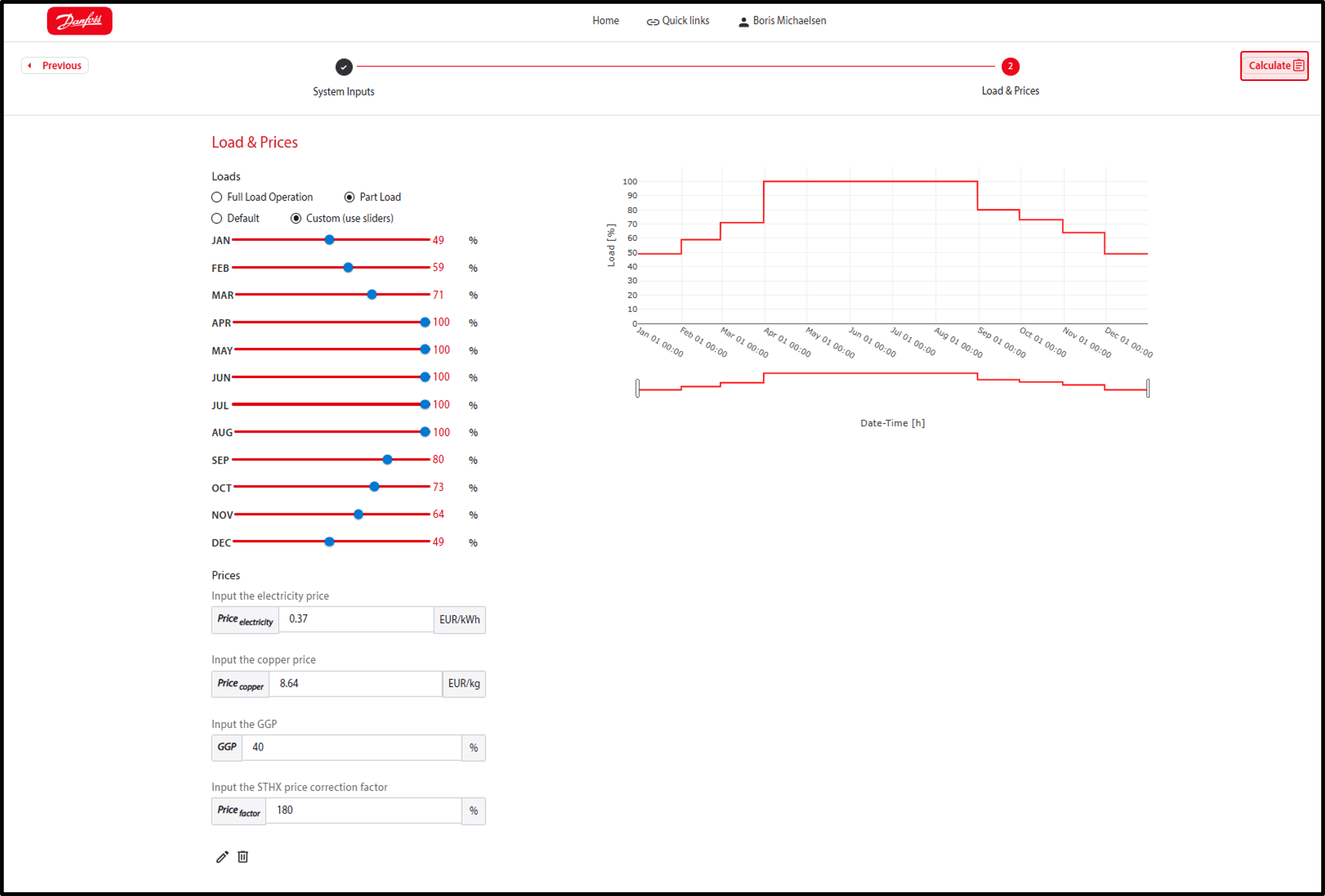
Load Profile
OPEX
CAPEX
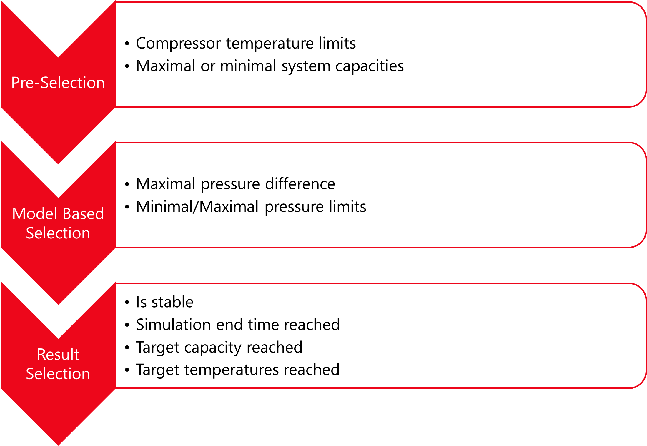
User input is used as parameter for the system models. These models will be simulated to select the best system in terms of efficiency, operating costs or capital investment. However, as there are thousands of possible variations, the system models are filtered first:
Compressors
Refrigerants
Design
Design
Design
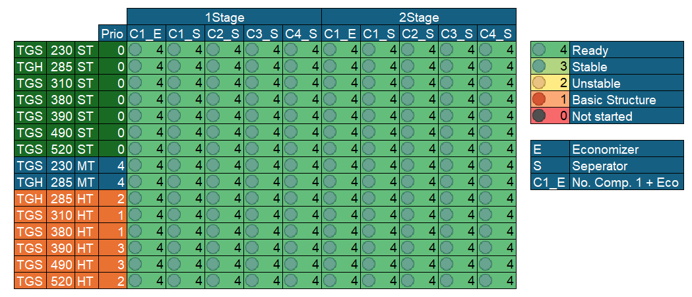
Variations:
Many more systems and variations are possible:

Start the selection:
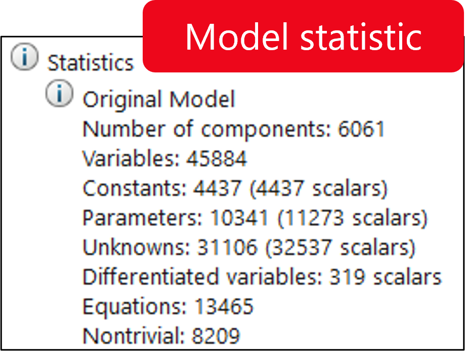
FMU Simulation
The following components are scaled by the requested capacity:
All components are initialized for a standard operating point.
After the simulation, the following calculations are performed:
Selection:
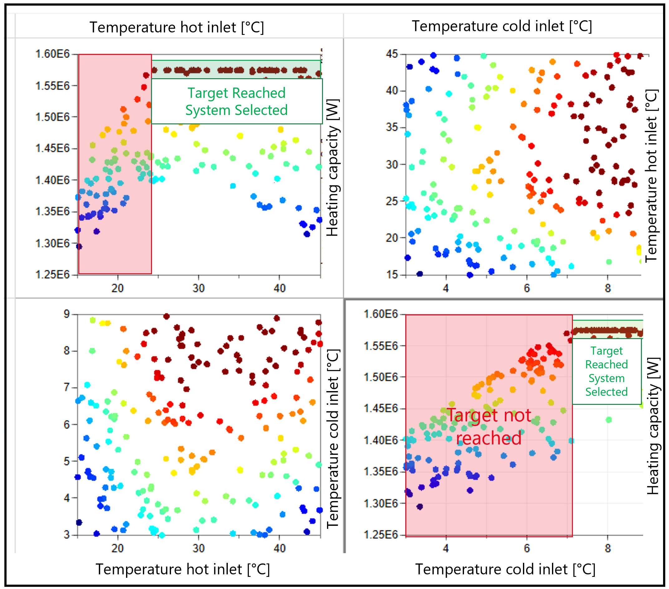
Selection:
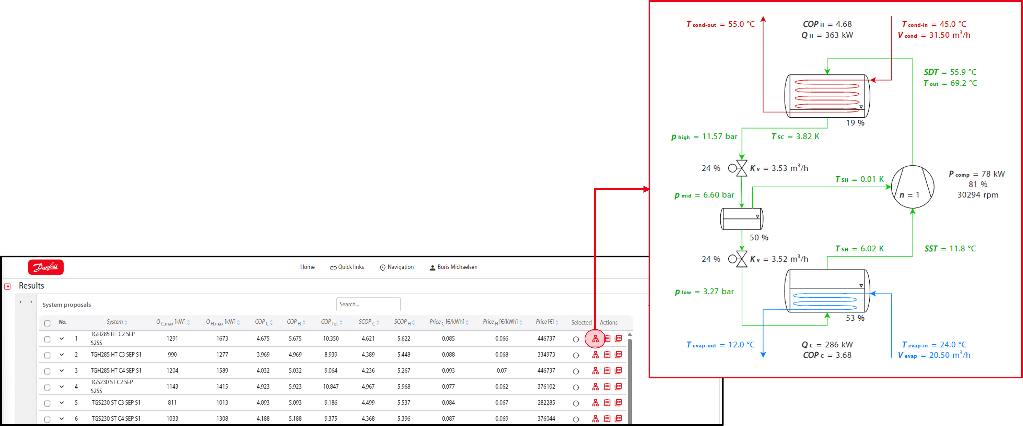
Preselection and system overview:
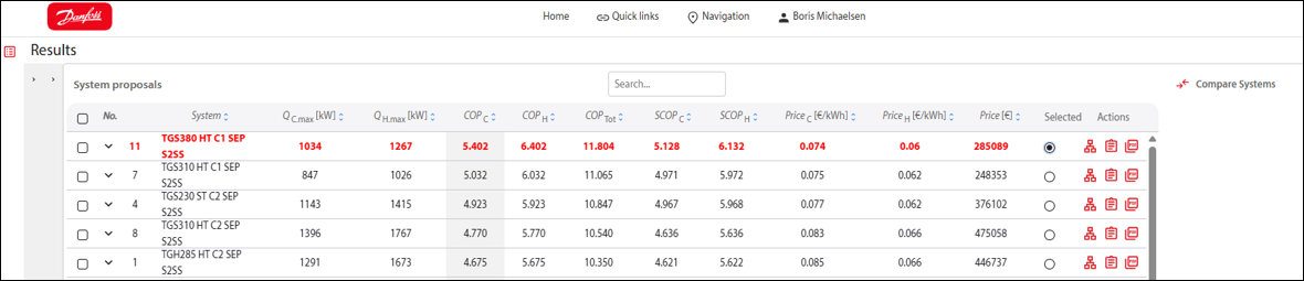
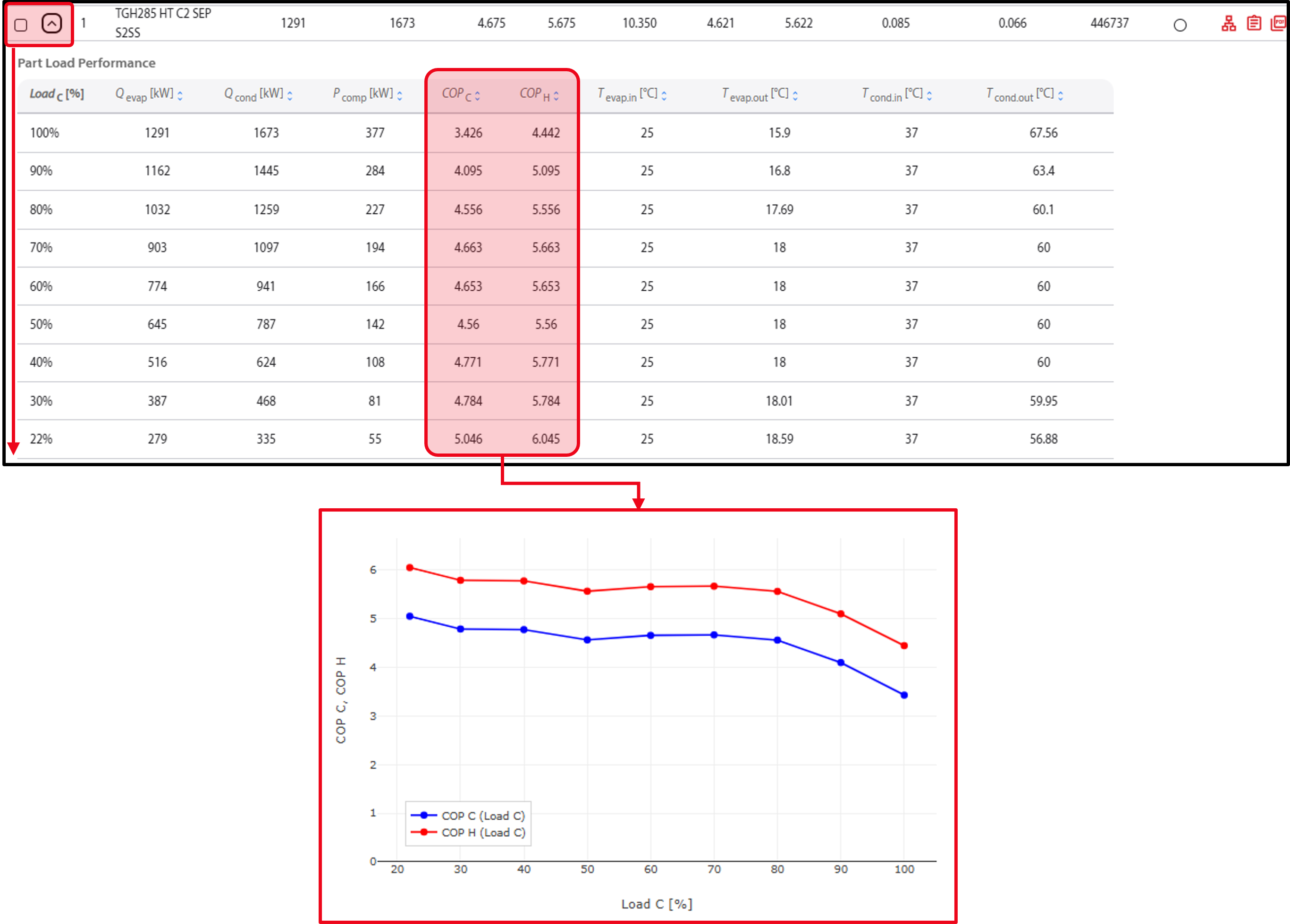
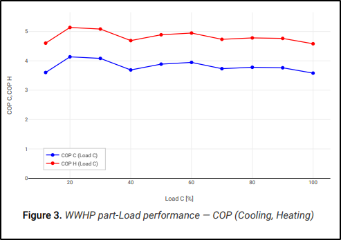
Part load performance:
Selection:


Selection:
Selection:

Selection:
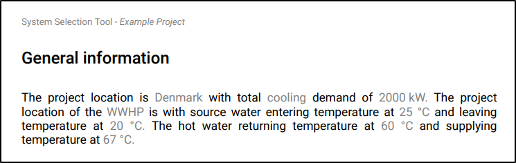
General information:
Selection:
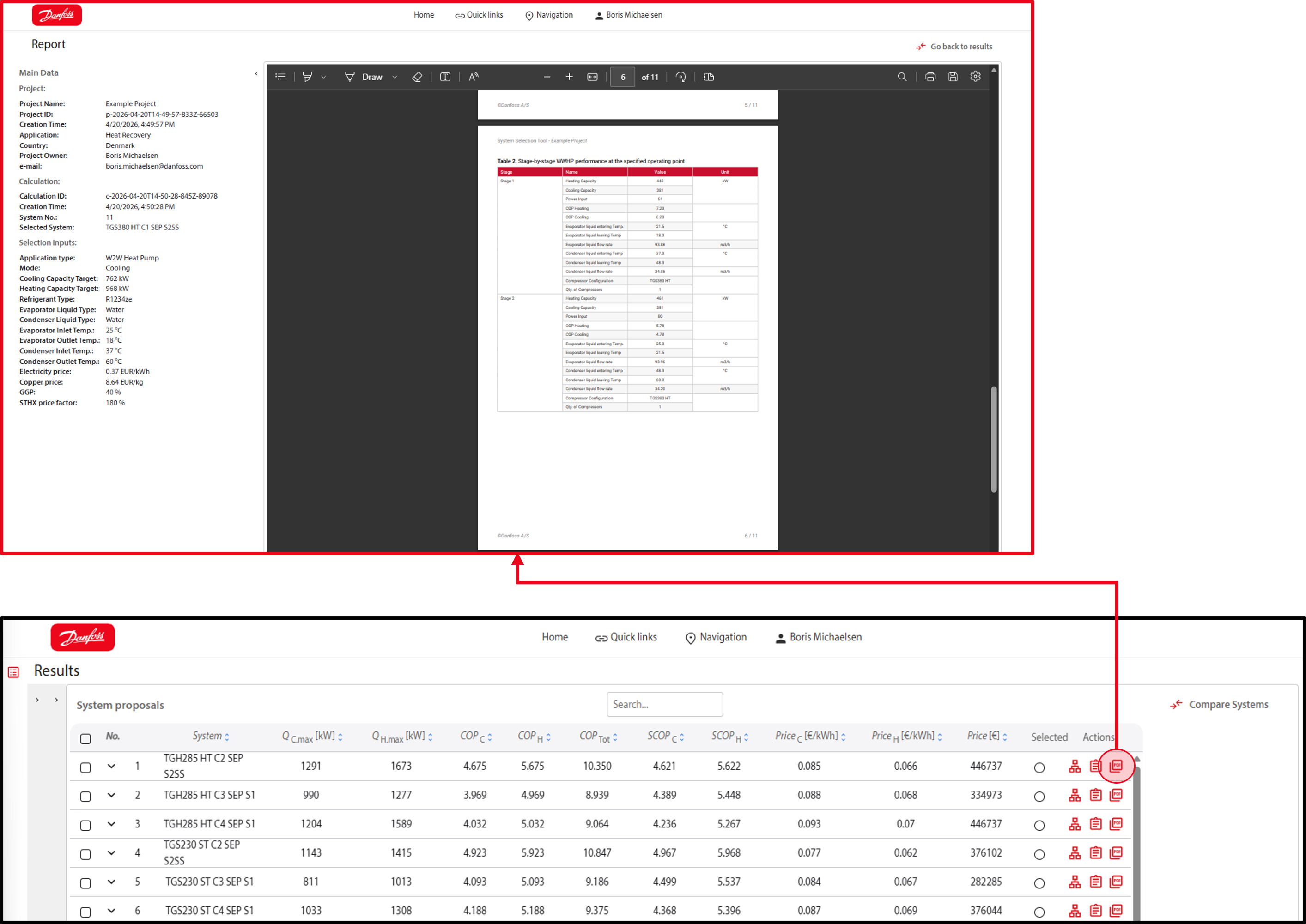
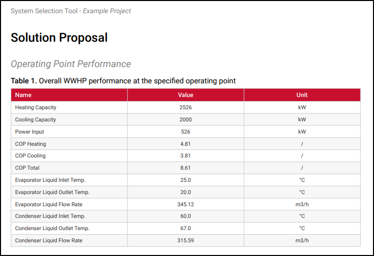
Operating point performance:
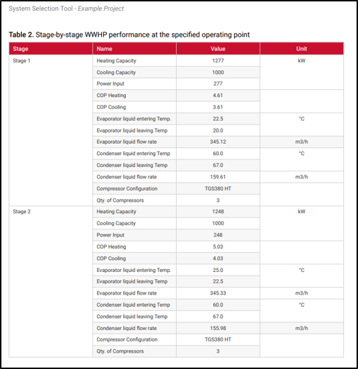
Operating point performance per stage:
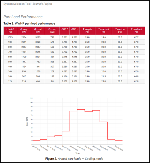
Part load performance:
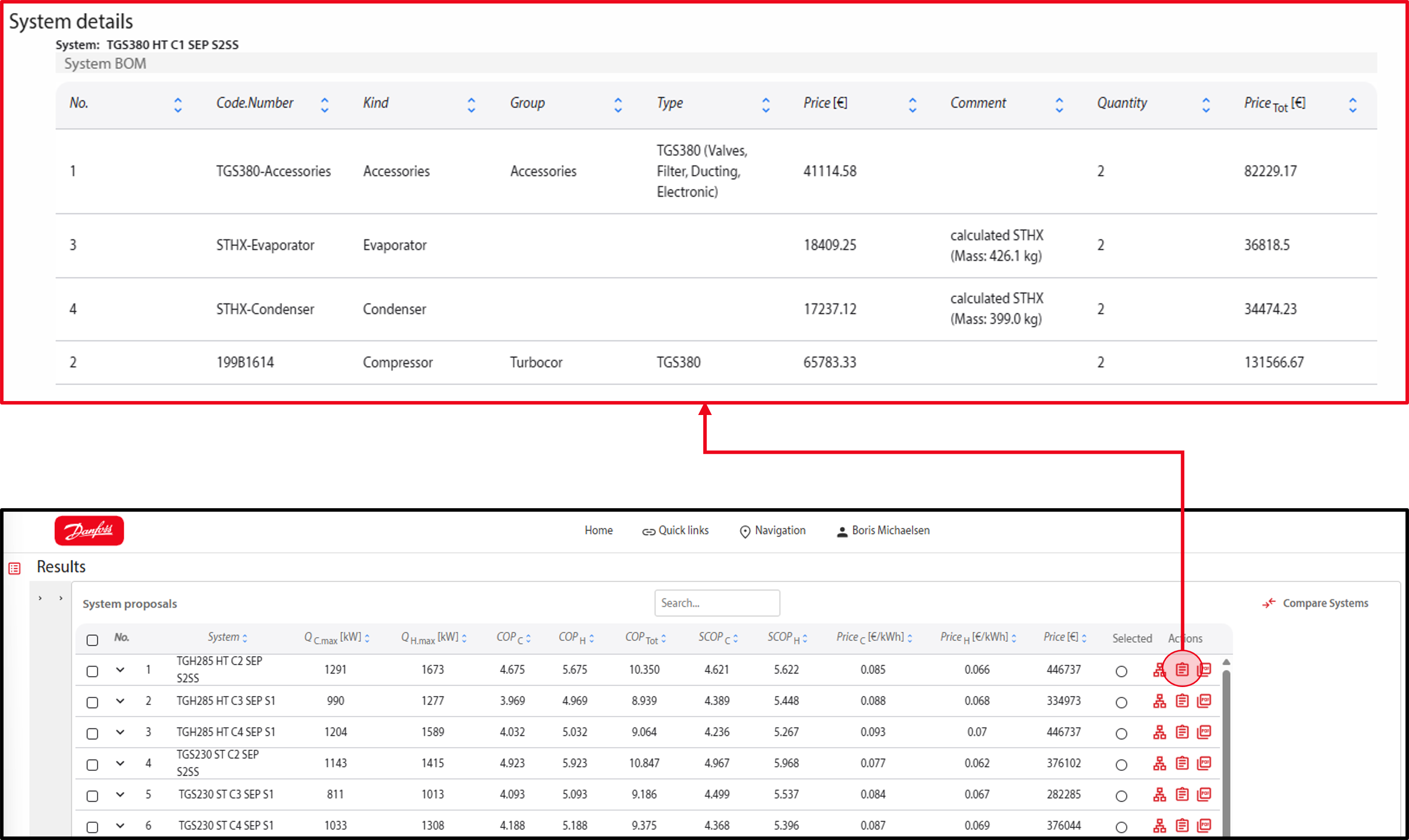
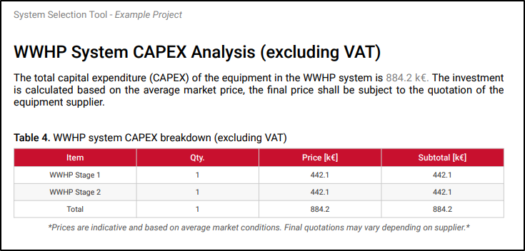
CAPEX:
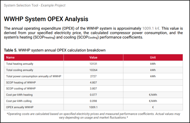
OPEX:
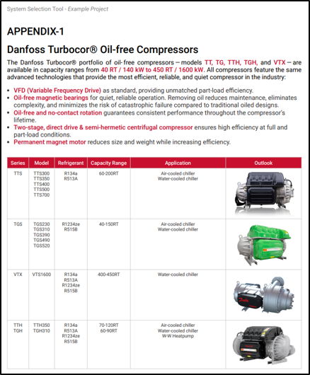
Product information on the components used and comparable products within the product range:
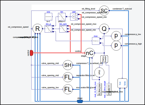
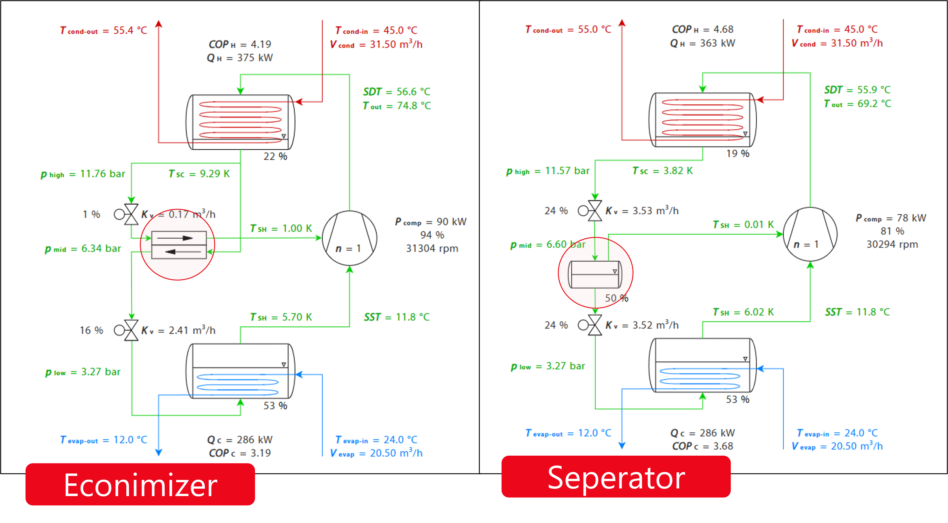
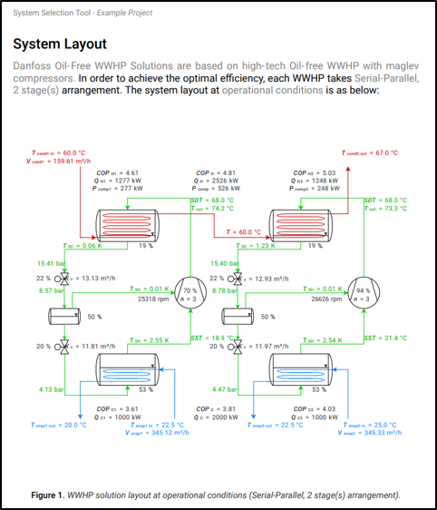
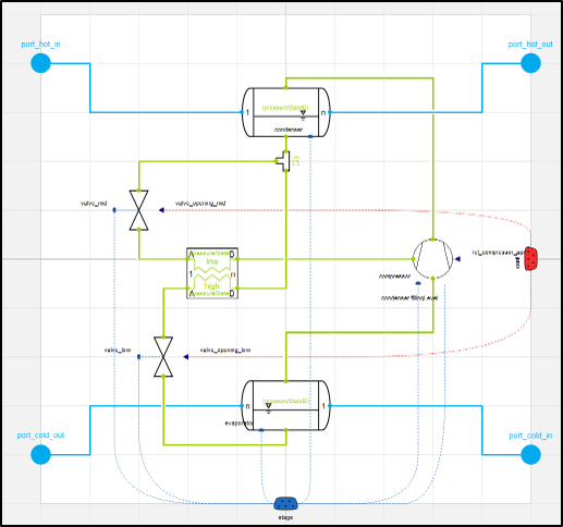
The two-stage refrigeration circuits used employ two control valves and the compressor speed to regulate the system. All systems and stages are controlled independently of one another.
Controlled components:
The system control block includes different control types: